Burnham BASE-RAY 81441001R8-3/06 User Manual
Browse online or download User Manual for Unknown Burnham BASE-RAY 81441001R8-3/06. Burnham BASE-RAY 81441001R8-3/06 User's Manual
- Page / 16
- Table of contents
- BOOKMARKS
Summary of Contents
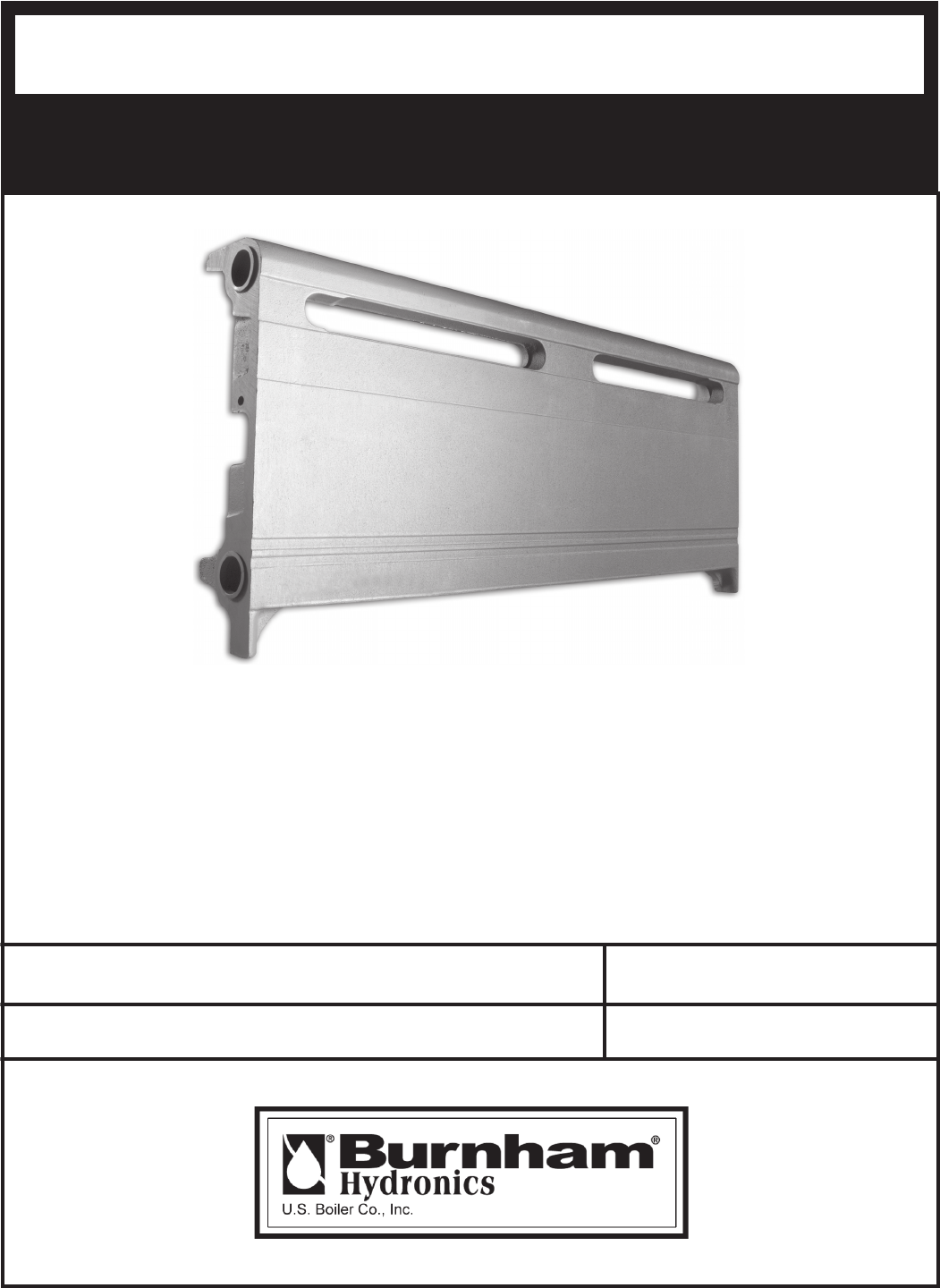
81441001R8-3/06Price - $2.00ROFLAUNAMNOITALLATSNIMAHNRUBAR-ESABY®PAGE 2 I=B=R RATINGS 4 ASSEMBLY CHART 5 SYSTEM TYPES 6 SERIES LOOP
105. Assembling BASE-RAY® BASE-RAY is shipped assembled in lengths up to six (6) lineal feet – longer assemblies are shipped in two or more sub-assem
11Stand Assemblies upright, place in position and fasten to the walls with Top Center Supports using the number shown in the table above. Insert Top
128. Installation of Corner PlatesINVERTED CORNER PLATES – for inside corners – furnished in two types, 4-5/8” standard plate is used when Assemblies
13 ADJUSTABLE END CAPS & FILLER PIECES – Adjustable End Caps are available in both left-hand and right-hand patterns and are used in the same loc
14SPECIAL APPLICATIONSBASE-RAY® INSTALLED ON THREE WALLS OF ROOM – When BASE-RAY is installed on three walls, expansion noises are sometimes created b
15All Base-Ray® repair parts may be obtained through your local Burnham Wholesale Distributor. Should you require assistance in locating a Burnham Di
Limited Warranty – Except as provided below with respect to products or parts not manufactured by U.S. Boiler Co., Inc. U.S. Boiler Co., Inc. warrants
2For Ratings at the following temperatures, multiply the 150° rating by the multiplier of the desired temperature.No. 9A Base-Ray®I=B=R Ratings – Stea
3For Ratings at the following temperatures, multiply the 150° rating by the multiplier of the desired temperature.Temperature – Multiplier150° - 1.0
4Dimensions and Speci¿ cationsBASE-RAY TAPPINGS- Tapped 3/4" top and bot- tom of end sections. A 3/4" x 1/8" vent bushin
5BASE-RAY® HYDRONICSTypes of SystemsHydronic Heating Systems are classi¿ ed according to the pip-ing arrangement and heating medium employed. BASE-RA
6SERIES LOOP SYSTEMSInstallation DataThis type of installation, in which the BASE-RAY®Assem-blies serve as part of the main, is the most economical wa
7To Design Series-Loop Base-Ray®Installation –1. Calculate the Heat Loss of each room using the procedure outlined in the I=B=R Heat Loss Calculation
8Installation DetailsA BASE-RAY® heating system is extremely easy to install – no other heating system requires less labor. The same installa-tion pr
9INSTALLATION INSTRUCTIONS1. Wall Preparation: To prevent excessive heat loss through the walls in back of BASE-RAY®, it is recommended that the stud
Related products and manuals for Unknown Burnham BASE-RAY 81441001R8-3/06
 (1 pages)
 (1 pages)
(22 pages)
(1 pages)
(4 pages)
(1 pages)
(1 pages)
(22 pages)
(1 pages)
(4 pages)
© 2020, manymanuals.com. All rights reserved. | 1.696 s |
 Manymanuals.com
 Manymanuals.de
 Manymanuals.fr
 Manymanuals.it
 Manymanuals.pl
 Manymanuals.cz
 Manymanuals.es
 Manymanuals-pt.com
Comments to this Manuals